Category:Meccano motors
.jpg)
1935: Meccano clockwork and electric motors [image info]
.jpg)
1939: "Build your own Electric Motors and Dynamos" [image info]
.jpg)
~1963: Meccano clockwork and electric motors [image info]
.jpg)
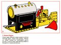
1978: Meccano motors - "The next step forward" [image info]
Inside the Meccano No.1 reversing motor
The motor casing is a pair of sturdy metal plates with Meccano holes around the edges, held apart by four spacers. There's a square winding key post on one side, and the output shaft is a Meccano rod threaded though a Meccano pinion that can be removed or adjusted so that the rod (or another, longer rod) can protrude from the winding side, the opposite side, or from both.
Behind the winding post is a large coiled flat strip spring, and behind that is a large gearwheel fitted with a slip ratchet arrangement so that the winding shaft can only wind in one direction.
This large gear (#1) drives a much smaller gear (#2, which has to rotate much faster to keep up. On the same shaft as #2 is a mid-sized gear (3), which engages with either one or two smaller gears depending on the reverse switch position, after which there's a small pinion which can be removed or replaced, and which is mounted on the final (removable, replaceable) output drive shaft.
Because of the multiple gearing stages, the output shaft runs much more quickly than the large gear attached to the unwinding spring, but is also considerably weaker.
Regulator and brake
Gear #2 also engages with another small gear on a shaft with a larger gear which then drives another small gear, giving another two boosts in rotation speed on the final shaft, which rotates very fast. This other output shaft is purely for control, and has two functions:
- Because of the extra gearings, the force available on this final high-speed shaft is extremely weak, and it can be stopped rotating with a tiny amount of friction. The brake lever applies the necessary friction, so that the motor can be stalled with a very light touch.
- The shaft is also fitted with a centrifugal regulator - The shaft has a hole drilled through it that takes an arm, holding a small brass weight on one side and a retention spring on the other. As this arrangement spins at high speed, there will be a critical speed at which the brass weight is thrown outwards by centrifugal forces enough to compress the spring on the other side, so that the weight extends and grazes the sides of a circular metal wall that is welded to the back of the upper plate housing, encircling the regulator. At this speed, the tine amount of friction (given the gearing) is enough to brake the motor until the speed reduces to a value at which the weight is barely touching the circular wall.
If the motor is designed to run naturally at a speed that makes the regulator cut in, then it'll run at a fairly constant speed no matter how tightly its spring is wound.
Subcategories
This category has the following 3 subcategories, out of 3 total.
M
- Meccano clockwork motors (6 P, 7 F)
- Meccano electric motors (4 P, 5 F)
- Meccano steam engines (4 P, 9 F)
Pages in category ‘Meccano motors’
The following 14 pages are in this category, out of 14 total.
M
- Meccano Aero Clockwork Motor No2 (Meccano M231)
- Meccano Clockwork Motor
- Meccano Clockwork Motor No1
- Meccano Clockwork Motor No1A
- Meccano Clockwork Motor No2, black, 1912 (Märklin for Meccano Ltd)
- Meccano Clockwork Motor No2, silver, 1912 (Märklin for Meccano Ltd)
- Meccano Electric Motor E020
- Meccano Electric Motor E20R(S)
- Meccano six-speed electric motor 228
- Meccano Steam Engine (Mamod for Meccano)
- Meccano Steam Engine, 1929 (Meccano Ltd)
- Meccano Steam Engine, 1935 (Meccano Ltd)
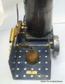
- Meccano Upright Steam Engine, 1914 (Bing for Meccano Ltd)
Media in category ‘Meccano motors’
The following 20 files are in this category, out of 20 total.
 Early Meccano steam engine, detail.jpg 931 × 1,200; 328 KB
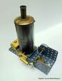 Early Meccano steam engine.jpg 904 × 1,200; 92 KB
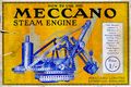 How To Use The Meccano Steam Engine, front cover.jpg 2,500 × 1,670; 1.47 MB
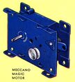 Meccano 'Magic Motor' (1935 BHTMP).jpg 604 × 668; 59 KB
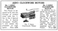 Meccano Aero Clockwork Motors (1939 catalogue).jpg 899 × 479; 120 KB
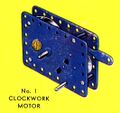 Meccano Clockwork Motor No1 (1935 BHTMP).jpg 529 × 499; 38 KB
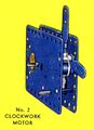 Meccano Clockwork Motor No2 (1935 BHTMP).jpg 476 × 658; 42 KB
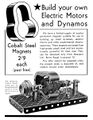 Meccano Cobalt Magnets (MM 1939-12).jpg 933 × 1,200; 222 KB
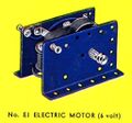 Meccano Electric Motor E1 (6 Volt) (1935 BHTMP).jpg 509 × 475; 36 KB
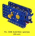 Meccano Electric Motor E20B (20 Volt) (1935 BHTMP).jpg 505 × 525; 44 KB
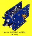 Meccano Electric Motor E6 (6 Volt) (1935 BHTMP).jpg 493 × 556; 43 KB
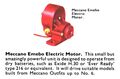 Meccano Emebo Electric Motor (MCat ~1963).jpg 1,655 × 1,090; 189 KB
 Meccano Motors (MCat ~1963).jpg 1,600 × 1,113; 391 KB
 Meccano Power Units (1935 BHTMP).jpg 1,650 × 1,204; 393 KB
 Meccano Steam Engine (MBoM234 1970).jpg 2,000 × 1,489; 1.03 MB
 Meccano Steam Engine (MM 1934-10).jpg 877 × 961; 88 KB
 Meccano Steam Engine, Mamod (MHMBM 1975).jpg 1,266 × 987; 899 KB
 The Meccano Steam Engine (MM 1935-01).jpg 2,600 × 1,676; 706 KB
 The Next Step Forward, Meccano (MBoM4 1978).jpg 3,000 × 1,822; 2.49 MB
 Vertical Steam Engine (MLCat ~1920).jpg 1,600 × 931; 187 KB


.jpg)
.jpg)
.jpg)
.jpg)
.jpg)
_(1935_BHTMP).jpg)
_(1935_BHTMP).jpg)
_(1935_BHTMP).jpg)
.jpg)
.jpg)
.jpg)
.jpg)
.jpg)
.jpg)
.jpg)
.jpg)
.jpg)