Grand Victorian Suspension Bridge (Tri-ang R264)
| in storage |
|---|
Grand Victorian Suspension Bridge (Tri-ang R264)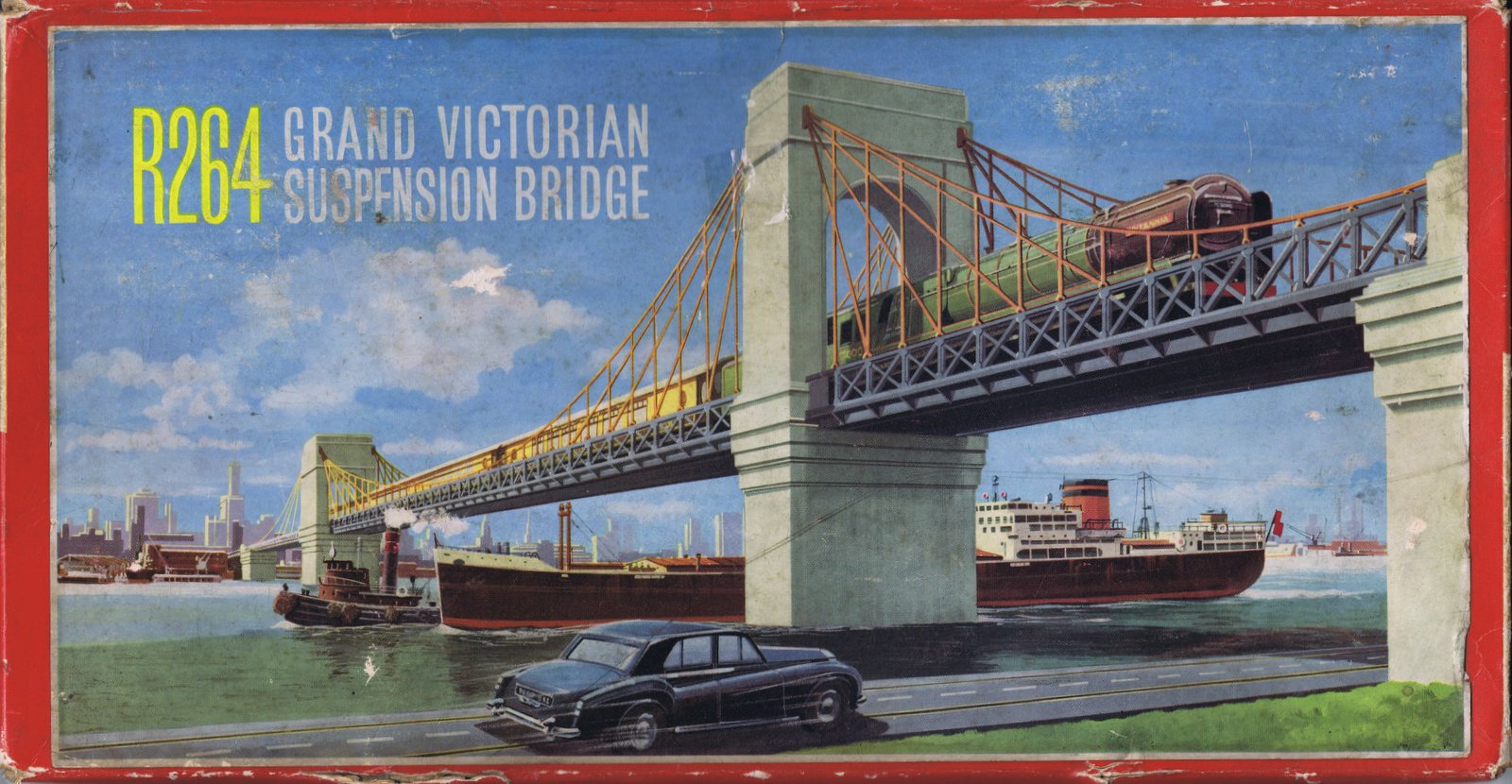 (i) (i)
|
|
|
| location: |
|
in storage |
Box lid [image info]
A four-and-a-half-feet-long Tri-ang R264 Grand Victorian Suspension Bridge.
The bridge is supplied as a plastic clip-together kit, with differently-coloured plastic for the piers, the railings, and the suspension cabling, the idea being that while it could be painted for a properly realistic effect, it didn't look bad just clipped together out of the box.
Although it's meant to be clipped together, this example may have warped slightly with age, and some of the suspension parts have a tendency to "ping" off when stressed. For permanent use on a layout, at least some of the parts would probably want to be glued, perhaps after painting.
Painting
As with the Tri-ang multicoloured clip-together building kits, the fact that the parts are pre-coloured has a serious bonus even for serious builders who intends to paint the whole thing: as all the parts that are different colours have been designed to be distinctly separate pieces, the modelmaker can simply paint each piece a single colour (except perhaps the surfaces to be glued) before assembly, and end up with an impeccably-edged finish, with no paint straying where it shouldn't be, or failing to quite meet an edge. This was also a feature of the Tri-ang kit houses, which let you easily create a "perfect paint job" on details such as window-frames, as these were separate pieces.
Use
While the R264 bridge was a classic piece of design, many layout builders who loved it could never justify buying one, as it was difficult incorporating it in a running layout. While bridges over land would tend to have many arched supports, suspension bridges tended to be reserved for spanning large, wide rivers or deep ravines, and most railway layouts are not large enough to accomodate a four-foot-wide river! The bridge could be useful as part of a way of connecting two separate railway layout sections, which might be divided by an access walkway, with the bridge part of a "drop-in" section.
Since the bridge is only made of plastic, the owner of a permanent installation might want to glue long reinforcng metal strips to the underside of the bridge to improve stability ... perhaps with a deliberate break in the middle, so that the bridge can still be partly disassembled.
Customisability
The bridge can be split into two main sections, each with a central pier and two cantilevered sections. This means that the kit can be used to make a half-length single-pier bridge, or two half-length bridges (with only two end supports), or, for truly massive applications, two or three kits could be used to build a truly huge nine-footer or thirteen-and-a-half footer bridge, perhaps as part of the backdrop of a layout. If used as a backdrop, with two tracks of n-gauge track, and n-gauge trains running back and forth and disappearing behind scenery at the ends, could make a nice sense of false perspective to an 00-gauge layout.
There's no obvious feature for converting the bridge into a two-track, double-arch bridge, other than putting two R264s side-by side. If one wanted to get really ambitious, the towers could be assembled and glued with a hole cut in the bottom, the hole used to fill the tower with a plaster-like filler), and then the sides of two adjacent towers sanded flat, and then glued together.
Filling at least the bases of the towers might be a good idea anyway from the point of view of stability, although completely filling the towers with solid plaster all the way to the top might make them a little on the heavy side if the bridge is to be moveable. Using a base filling-hole, part-filling, then plugging the hole and righting the tower while the plaster sets would give a combination of solidity and low centre of gravity ... but since the filling-hole would then be blocked, you wouldn't be able to then decide to "top up" the plaster at a later date.
Overall impressions
The bridge builds to a two-pier suspension bridge, which looks really very imposing: it gives the impression of having been based on something really quite large. This impression is slightly spoiled when you realise that it only takes a single line of 00-gauge track. Although the basic suspension-bridge design "scales" well, and has no fixed size, R264 gives the impression of being designed as a truly massive bridge, and the spell is broken when you run am 00-gauge train through it. We think that the bridge would look better with a run of TT scale track, or even better, with two tracks of N gauge, side by side.
Or, just use it in the background, to give the impression of a huge bridge in the distance.
Original design
The bridge does not seem to have been modelled on a specific original.
Part of the impression that this is supposed to be a large and imposing bridge may be because most of the suspension bridges that we are familiar with nowadays are very large, making it seem anomalous that this could be a narrow bridge only capable of a single track. However, some of the earliest suspension bridges were comparatively small, and did only run a single line of track.
They were also often not very successful, and tended to be demolished and replaced. Part of the reason for this is that suspension bridges had a habit of swaying and oscillating and showing strange behaviours if presented with a very uneven loading, or when subjected to oscillating forces. Loading for a road bridge o footbridge would normally be fairly even, but with a railway bridge, at one point the train might occupy the first half of the bridge, which could be at maximum load while the second half is empty, and shortly afterwards, the second half of the bridge could be fully loaded while the first half was completely empty. This worst-case uneven loading could push a small suspension bridge to the limits of its design (or beyond!).
With steam locomotives there was an additional problematic effect of "hammer blows" ... when a steam loco has multiple drive wheels, these are usually connected together on each side of the engine with a very heavy-duty (and very heavy) coupling rod. This was necessarily strongly off-centre, and the reaction forces when these rods cycles in their position each time the wheels turned, created repetitive down-forces on each set of drivewheels, "hammering" the track. While this hammer action was bad enough on normal track, in a suspension bridge that might have all sorts of resonant frequencies, the effect could be disastrous.
External links
- Hornby R8008 Grand Suspension Bridge - Based on any particular prototype? (rmweb.co.uk)
- Modifying the Hornby Grand Suspension bridge (keymodelworld.com)
- R8008 Grand Suspension Bridge (uk.hornby.com)

