Category:Anchor Engineer
| Toy Brands and Manufacturers |
|---|
|
Anchor Engineer |
| 1914 - 1920s |
.jpg)
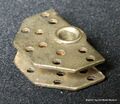
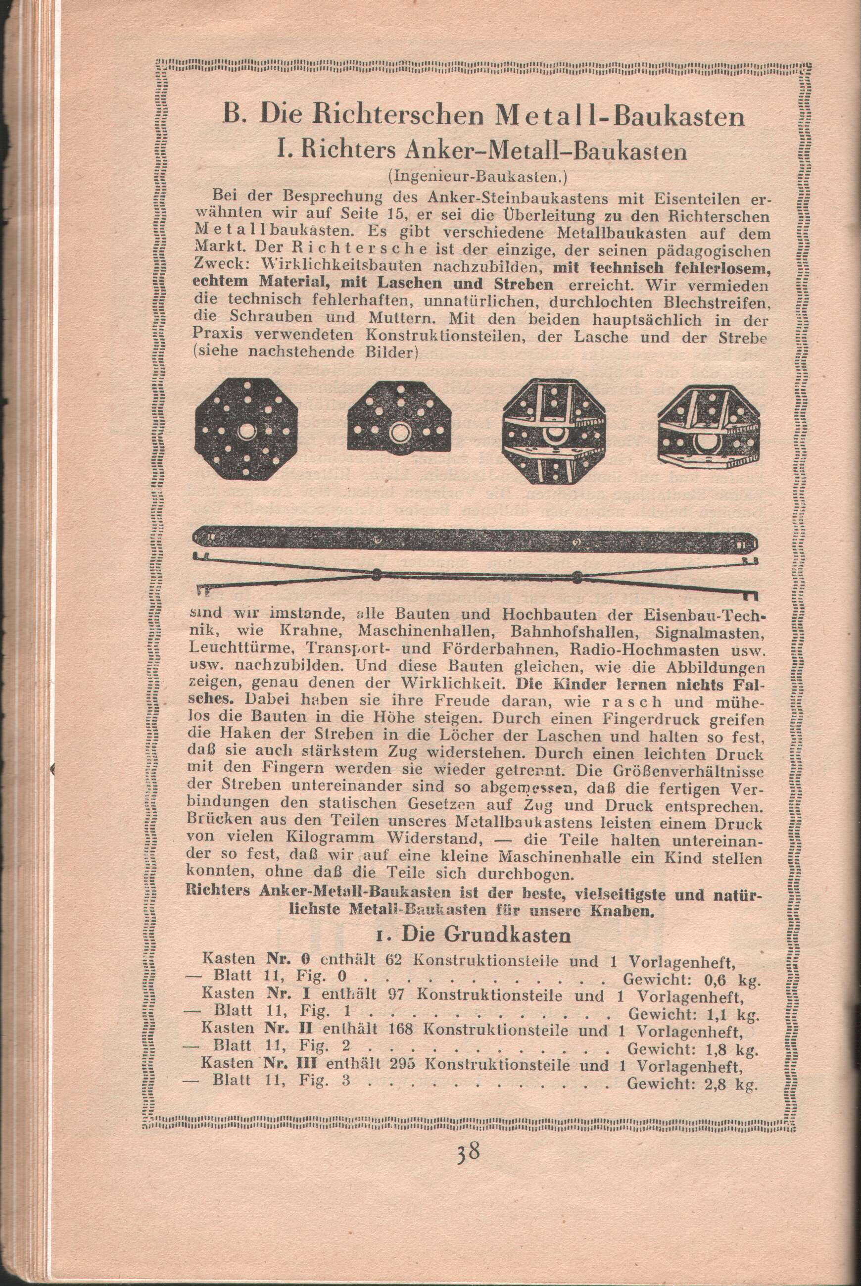
180×180×90-degree plate, with opposing pairs of double-holes for clipping struts into place [image info]
.jpg)
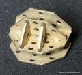
180-degree "flat" plate [image info]
.jpg)
Anchor Engineer construction sets, 1924 [image info]
.jpg)
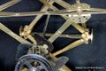
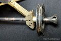
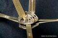
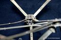
A 180×180×90-degree plate with five struts attached at different angles, with a combination of fixed and pivoting joints [image info]
.jpg)
Another view of the same joint [image info]
.jpg)
Anchor Engineer model examples, 1924 [image info]
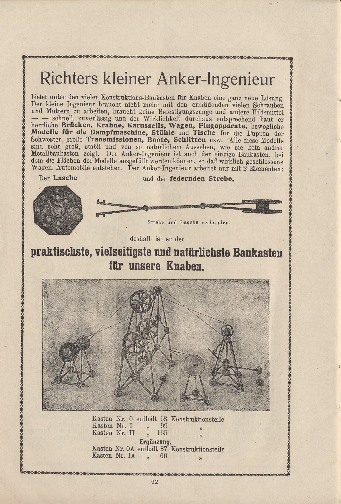
Anchor Engineer (Anker Ingenieur) was Richter's attempt to get into the business of making metal construction toys.
The system was originally designed and patented by Franz Hendrichs, who submitted the German patent application in early 1912, and had his UK patent application accepted in May 1913.
While other metal construction systems often tried to copy Meccano, Anchor Engineer was quirkily original, composed of a system of metal hubs and struts with sprung ends that clipped into them (referred to by Anchor as Plates and Stays).
Franz Hendrichs
Franz Hendrichs is listed in his patent application (GB 1913 03646) as being a Chief Engineer, residing at 28 Lindenallee, Charlottenberg, Germany.
We don't know whether this might be the same Franz Hendrichs who patented a number of inventions to do with cutlery manufacture and knife-grinding, and who lived for a while in Solingen, Germany's traditional sword-and knife-making region (the closest equivalent in the UK being Sheffield). That Franz Hendrichs also wrote extensively on the history of Solingen and metal-working in Germany ... so if they were the same person, this might explain the unusual design of the system, which would seem to have been conceived by someone with a background in metalworking, but with an emphasis on more expensive "solid" craftsman techniques used, for working thick metal and hafting, rather than mass-market toymaking.
Parts
The Strut
The struts consisted of a pair of thin parallel metal strips, riveted together at two points along their length, and splayed apart at the ends. These springy "leaf" ends could then be pushed together and inserted into a gap in the hub piece, and would then push outwards against the hub cavity walls.
The struts also had a couple of outward-facing prongs punched into the end of each strip leaf, which could engage with holes in the hub wall. If both prongs engaged, with two hub holes (on each side), then the strut would make a rigid connection with the hub. If the strut was only partly inserted, so that only the endmost set of prongs engaged with a pair of holes, the joint allowed swivelling.
The Hub
The basic hub-plate consisted of a sturdy pair of parallel octagonal plates joined by a hollow collar that could take a shaft. Both plates had eight pairs of radiating holes, allowing up to eight radiating struts to be clipped to it at multiples of 45 degrees - ideal for making a fairground Big Wheel.
The sets then included a range of variations on the basic hub design – for a Ferris-wheel, the radiating spokes would then have to be terminated with additional hubs and linked by cross-members ... but these hubs wouldn't need to support connections at every angle, so a smaller "cut-down" version of the piece with five sets of radiating holes rather than eight could be used, and there were also variations with additional plates set at 90 degrees to the standard plates, allowing more struts to be connected outside the plane.
Other parts
The sets also included axles which could be threaded through the hub centres, wheels to be fitted onto the axles, a slightly odd part for locking a wheel to an axle ... and a rather odd angled part whose intended use we don't know! The larger sets also included a circular saw and a grindstone (not an obvious choice for a metal construction set, but easy for Anchor to make, considering their main manufacturing business of artificial stone blocks).
1924 Promotional text
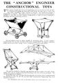
THE "ANCHOR" ENGINEER CONSTRUCTIONAL TOYS
NO Screws. NO Bolts or Nuts, NO Auxiliary Tools.
The "ANCHOR ENGINEER" works with two elements only
- The Plate
- The Stay
Magnificent Bridges, Cranes, Flying-Machines, Roundabouts, and all kinds of working models can be built with the greatest ease.
THIS system of metal parts for model engineering structures involves no bolts and nuts. It is devised with spring clip beams and struts, fitting into joint units in such a way that when completed a rigid structure is obtained. The well-known principle of triangulation is adopted. The parts are more or less made to scale and are ingeniously proportioned so that they can form complete triangle girders of rigid form such as are employed in all bridges and other engineering structures.
The real engineer rivets his beams together by connecting angles. In the "Anchor" Constructional Toy the nibs provide don the beams engage holes in the separate connecting pieces, two or four of these spring "rivets" being used as occasion may require.
The parts are finished in a beautiful egg-shell black and are complete with shaft, wheels, pulleys and cords in various proportions according to the value of the set purchased. The sets are progressive in character.
Instructions and scale drawings with photographic illustrations of the completed models are included in each set, and all sets form ideal Constructive Engineering Toys of an instructive character.
Sets
- No. 0.
- This is the junior set of Anchor Engineer. Although it is a small and simple set, it contains parts, girders, pulleys and rods to make a great number of models that will fill endless hours with amusement and interest
- No. 1.
- This is the next size of Anchor Engineer – bigger and capable of building more advanced models than the junior with which it can be combined. This is the utmost value in toys that can possibly be offered.
- No. 0 Set, complete in box, makes 26 models ... ... 4/6
- No. 1 Set, complete in box, makes 32 models ... ... 4/6
- No. 2 Set. Larger than those illustrated, complete in box, makes 52 models ... ... 4/6
Supplementary Boxes, for adding the above
- No. 0a ... ... 4/-
- No. 1A ... ... 8/-
Parts List
The parts lists we've seen don't have part names, just outlines and part numbers, so the names below are descriptive rather than official.
- 501 Strut
- 502 Strut
- 504 Strut
- 505 Strut
- 511 Partial Hub Plate
- 512 Standard Hub Plate
- 513 Partial "3D" Hub Plate
- 514 "3D" Hub Plate
- 521 Small Four-Spoked Wheel
- 522 Large Six-Spoked Wheel
- 531 Winding Handle
- 533 Axle Lock
- 534 Axle
- 535 Axle
- 536 Axle
- 537 Axle
- 551 ??? plate
- 553 Grindstone
- 554 ??? (outline - cottonreel perhaps?)
- 557 Circular Saw
Links and references
- George F. Hardy, Richter’s Anker (Anchor) Stone Building Sets (2014) chapter 16, page 123- – .pdf file
- Product paperwork scans:
- Catalogue page scans:
Pages in category ‘Anchor Engineer’
This category contains only the following page.
Media in category ‘Anchor Engineer’
The following 10 files are in this category, out of 10 total.
 Anchor Engineer constructional sets (BL-B 1924-10).jpg 1,491 × 2,186; 454 KB
 Anchor Engineer constructional sets examples (BL-B 1924-10).jpg 1,530 × 2,157; 508 KB
 Anchor Engineer logo.jpg 400 × 311; 102 KB
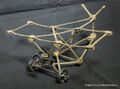 Light monoplane model (Anchor Engineer).jpg 1,405 × 1,045; 1.13 MB
 Model aeroplane, detail (Anchor Engineer).jpg 1,200 × 800; 528 KB
 Model aeroplane, detail, wheel and axle mounting (Anchor Engineer).jpg 2,200 × 1,467; 1.75 MB
 Plate, 180-degrees (Anchor Engineer).jpg 800 × 694; 329 KB
 Plate, 180×180×90 degrees (Anchor Engineer).jpg 1,200 × 1,102; 784 KB
 Plate, 360×180×180, attached (Anchor Engineer).jpg 1,600 × 1,067; 853 KB
 Plate, 360×180×180, attached, face view (Anchor Engineer).jpg 3,200 × 2,134; 3.73 MB
.jpg)
.jpg)
.jpg)
.jpg)
.jpg)
.jpg)
.jpg)
.jpg)
.jpg)

